
CDEDS (Constraint Driven Engineering Design Synthesis) Methodology
Abstract
A typical new product design passes through stages of – statement of need, development of concepts, synthesis of geometry, detailed product design, analysis and optimization. Significant time is spent in developing (Phrasing) and synthesizing (Detailing) concepts. Today, engineers use iterative methods and multiple tools to achieve the desired design goals which can be time consuming and non-optimal. This document describes a new methodology to improve the design process.
The methodology works on the premise that: if multiple limiting configurations can describe the working envelop of the mechanism and if customer needs can be expressed as design constraints then the problem reduces to solving a multi-objective optimization problem. The methodology also states that with appropriate software tools a pareto optimal solution that best reflects the engineers experience can be derived. This solution is superior to a solution derived using brute force iterative method because it encapsulates all the customer needs and working conditions into the problem at one go, thereby reducing design cycle time considerably and providing an opportunity to integrate an organizations product design philosophy into the solution.
Video
Introduction
Design1 is defined as creation of new things and Synthesis is the creative step itself in conceiving new solutions to solve a problem. While, Design addresses both creative and analytical aspects of the problem, Synthesis is an aspect of design which creates candidate solutions. Engineering is a subset of these design activities and it focuses more on the technical aspects of performance of designed systems.
Understanding the process of Engineering Design Synthesis is therefore key to defining effective methodologies and selection of appropriate software tools. As all things engineering, getting a well-conceived working solution to a problem is a preferred goal over mere concept generation. Therefore, we would consider generation of multiple (and innovative) concepts as only an intermediate step in the overall scheme of Engineering Design Synthesis. It follows that the methodology has to necessarily recognize two stages of Design Synthesis: “Concept Phrasing” (non-detail) and “Concept Detailing” stages.
Different Stages of CDEDS Design Synthesis
Concept Phrasing
During the creative stage of “Concept Phrasing”, an engineer is interested in answering the “how” of the problem. Multiple concepts are to be invented and evaluated. Conditions of acceptance typically relate to form and function and less to fit, physics or performance. Using a door flap example, let’s see how a simple functional requirements for an office cabinet door flap pans out in real life.
Key take-away from “Concept Phrasing” example:
The first three concepts above, differ vastly from one another on how they approach the problem and so the mechanisms are also different. The fourth one, is a variation of the parallelogram concept 3. This clearly shows that in the early stages of phrasing we need variety and also a bulk of ideas. As we progress through understanding the operating limitations of the door flap in greater detail, some candidate concepts get transformed into solutions. Evolution of mechanism from simple to complex, and vice-versa, is universally true for most projects where engineers get to understand the functional constraints better as they plough through detail. Seeing the operational constraints early during ideation saves time and cost compared to seeing them later in the project life cycle.
One can also notice that different working mechanisms result from different functional constraints being overlaid on the basic specification. These constraints, more so during Phrasing, can be translated to fundamental physical parameters like dimensional height, weight, area etc which are easily managed by today’s software.
To sum it up – creativity is the key driver during Concept Phrasing and we believe (at least for now) this firmly rests with the (human) engineer. The concepts can be sketched by hand or drawn using software but the key requirements are – variety and bulk. However, in order to tests the concepts one needs graphical software tools that are easy to use and have some simulation capability. It will be added advantage if the tool can also handle dimensions, as then, concepts can be tested against real-life functional constraints.
Concept Detailing
In “Concept Detailing”, one (or more) concepts from phrasing stage are typically subjected to Engineering rigor. Make no mistake, engineering parameters of fit and physics are just another set of boundary constraints laid over the concepts. They are integral to making concepts practical beyond just dimensional requirements. Depending on where you would want to stop, this step can actually end in well-conceived design solutions that are practical, meet engineering rigor and more importantly meet marketing specifications.
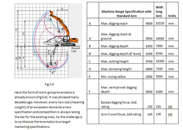
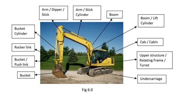
An excavator example below shows the challenges of “Concept Detailing”. This should help in selection of appropriate tools to address this stage of Engineering Design Synthesis.
Excavator example:
Design Specification: Design an excavator work group (circled in Fig 5.0 below) for a 23 ton tracked excavator that includes a boom, a dipper arm and a 1.2 cu.m bucket that delivers the range dimensions given. The boom pivot point on the turntable should be at least 1200 mm from ground and at least 100 mm from slew centre to provide clearance for other machinery:
The Engineering Manager can be in three different situations relating to this requirement and he would react differently for each situation:
Situation 1: The specification is an extension of an existing design within the factory: then the kinematic lengths of boom, dipper and bucket are almost known and the problem reduces to iterating the four-bar mechanism at the bucket end and arriving at the cylinder sizes.
Situation 2: The specification is of a competing machine not within the factory: then the manager would conduct a competitive bench-mark exercise and arrive at starting lengths from the study.
Situation 3: Specification is not a known configuration anywhere in the market: If you address this last situation, then other situations are automatically addressed.
Current engineering practices use elaborate and iterative methods to synthesize the geometry. The marketing specification are the design targets to reach and there aren’t many software, commercially available, that can synthesize the workgroup kinematics to satisfy all parts of specification at one go. You can work out preliminary kinematics in any 3D or 2D CAD software to satisfy the reach dimensions but then vertical wall depth may not be met. You could get the vertical wall and swing radius too if you are lucky, but then the forces become a consequence of that particular geometry. Worse still, the force calculations have to be accomplished on another software, and often, these two software cannot be dynamically linked. You then either live with what you get if it is “close enough”, or spend more hours iterating the kinematic design between multiple software.
Additionally, there are parts to workgroup design that are unstated in the specification that an engineer has to recognize upfront, to avoid problems later in the designs. For instance, an engineer has to recognize that heaviest pieces of the machinery are better closer to the machine to avoid problems in lift performance during working. Weight and forces automatically relate to stresses, stresses to section sizes and so on. Similarly there will be space claim issues relating to hydraulic cylinders, transport dimensions in folded condition, clearances to other machine parts like undercarriage, cab etc. Therefore “All” stated specification and unstated design criteria have to be recognized and, like in Concept Phrasing, have to be translated to boundary conditions or design constraints. Once the constraints are identified, solution to the problem can be found by applying the following methodology, described broadly below:
Each specification parameter, say maximum reach, is a configuration arising from two things – the kinematic lengths (of boom, dipper arm and bucket) and a particular orientation of the parts, in this case all stretched out. Therefore, if the kinematic lengths are defined as variables, then a configuration, say max reach, is a just a mathematical function of these variables.
Since different configurations arise from just changes to orientation of the parts, we recognize that lengths between pivot points should remain same between the different configurations. We can model other specification parameters, max depth, cutting height etc., using the same variables for length between pivots.
Other design criteria, can now be brought in as either more variables or more mathematical functions. For instance the SAE standard defines the digging forces to be applied in a particular orientation of dipper and bucket and at certain operating pressures conditions. Once we have equations for forces, section stresses can be described and consequently weight of parts can be estimated.
This methodology now suggest that the design synthesis problem can be solved numerically by applying multi-criteria optimization methods to the specification targets now described as Objective functions. Simpler problems like those of door flap or Situations 1, 2 described above, can be solved using simpler numerical optimization methods.
The seed/start/guess values for variables of lengths between pivots can always be generated from regression analysis of dimensions over weight of machine for different sizes. This is known to work.
Without getting into deeper discussion on Optimization, problems like the full-blown excavator work group design do not have a unique solution and so we seek a Pareto optimality which is a trade-off between different objective functions. There is a better chance of convergence if more variables are given bounding values reflecting design engineers preference or experience.
CDEDS Methodology Summary
We can now summarize the overall methodology for effective Engineering Design Synthesis as follows:
- Attempt to get a variety and bulk of ideas in the Concept Phrasing stage. More concepts can be generated by adding/removing functional requirements arising from context of application.
- A tool that enables simplified modelling, should be used to distil the concepts to a handful of candidate solutions. The software tool should have some simulation capability and should be able to handle dimensions. However, the key word is “simplicity”.
- Once a concept is chosen, to bring engineering rigor, express all functional requirements as constraint variables of either dimension, weight, force or some physical parameter that enables further use of software tools.
- Ensure that the selected software can handle all forms of constraint expression. A dead 2D drawing tool, 3D sketcher, spreadsheet, popular math and simulation tools when used individually are all seriously handicapped for Engineering Design Synthesis work. Sadly, math tools do not have the deep graphical capability of a CAD sketcher and the sketcher cannot do explicit math.
- Build a math model describing various operating conditions as configurations. The configurations are nothing but Objective functions for optimization.
- Key step: Solve the math model numerically as multi-objective optimization problem. This guarantees that that ensuing solution is a consequence of the “Simultaneous Action” of all the Design constraints.
- Fine-tune the solution by defining bounding values for constraint variables.
Conclusion
Whether such an interlinked mathematical description of geometry and constraints is possible would depend on the quality of the software tool(s) used for the purpose of Design Synthesis. And whether such a construct would result in a viable engineering solution would depend on the skill of the engineer. The ultimate measure however is the quality of the engineering solution delivered.
References:
1. Formal Engineering Design Synthesis, Edited by Erik K. Antonsson and Jonathan Cagan, Cambridge Press
2. The concept diagrams are a small sample from a large number of patents on “Actuating mechanism for moving an upwardly movable flap of a piece of furniture” http://www.google.co.in/patents/US8376480
Concept 2A is patent US4783131 (1988), Concept 2B is patent # US7168477 (2007), Concept 3 is #US7797796 (2010) and Concept 4 is #US8376480 (2013).
Ravindra Bachalli
Mechanical Design Engineer